PROCESSORS AND HEAT SINK SECRETS

Central processing unit

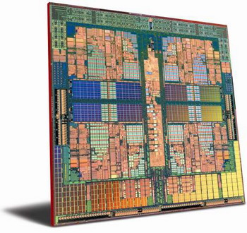
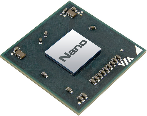
The central processing unit (CPU) is the portion of a computer system that carries out the instructions of a computer program, and is the primary element carrying out the computer's functions. The central processing unit carries out each instruction of the program in sequence, to perform the basic arithmetical, logical, and input/output operations of the system. This term has been in use in the computer industry at least since the early 1960s.[1] The form, design and implementation of CPUs have changed dramatically since the earliest examples, but their fundamental operation remains much the same.
Early CPUs were custom-designed as a part of a larger, sometimes one-of-a-kind, computer. However, this costly method of designing custom CPUs for a particular application has largely given way to the development of mass-produced processors that are made for one or many purposes. This standardization trend generally began in the era of discrete transistor mainframes and minicomputers and has rapidly accelerated with the popularization of the integrated circuit (IC). The IC has allowed increasingly complex CPUs to be designed and manufactured to tolerances on the order of nanometers. Both the miniaturization and standardization of CPUs have increased the presence of these digital devices in modern life far beyond the limited application of dedicated computing machines. Modern microprocessors appear in everything from automobiles to cell phones and children's toys.
Contents[hide] |
[edit] History

Computers such as the ENIAC had to be physically rewired in order to perform different tasks, which caused these machines to be called "fixed-program computers." Since the term "CPU" is generally defined as a software (computer program) execution device, the earliest devices that could rightly be called CPUs came with the advent of the stored-program computer.
The idea of a stored-program computer was already present in the design of J. Presper Eckert and John William Mauchly's ENIAC, but was initially omitted so the machine could be finished sooner. On June 30, 1945, before ENIAC was completed, mathematician John von Neumann distributed the paper entitled First Draft of a Report on the EDVAC. It outlined the design of a stored-program computer that would eventually be completed in August 1949.[2] EDVAC was designed to perform a certain number of instructions (or operations) of various types. These instructions could be combined to create useful programs for the EDVAC to run. Significantly, the programs written for EDVAC were stored in high-speed computer memory rather than specified by the physical wiring of the computer. This overcame a severe limitation of ENIAC, which was the considerable time and effort required to reconfigure the computer to perform a new task. With von Neumann's design, the program, or software, that EDVAC ran could be changed simply by changing the contents of the computer's memory.
While von Neumann is most often credited with the design of the stored-program computer because of his design of EDVAC, others before him, such as Konrad Zuse, had suggested and implemented similar ideas. The so-called Harvard architecture of the Harvard Mark I, which was completed before EDVAC, also utilized a stored-program design using punched paper tape rather than electronic memory. The key difference between the von Neumann and Harvard architectures is that the latter separates the storage and treatment of CPU instructions and data, while the former uses the same memory space for both. Most modern CPUs are primarily von Neumann in design, but elements of the Harvard architecture are commonly seen as well.
As a digital device, a CPU is limited to a set of discrete states, and requires some kind of switching elements to differentiate between and change states. Prior to commercial development of the transistor, electrical relays and vacuum tubes (thermionic valves) were commonly used as switching elements. Although these had distinct speed advantages over earlier, purely mechanical designs, they were unreliable for various reasons. For example, building direct current sequential logic circuits out of relays requires additional hardware to cope with the problem of contact bounce. While vacuum tubes do not suffer from contact bounce, they must heat up before becoming fully operational, and they eventually cease to function due to slow contamination of their cathodes that occurs in the course of normal operation. If a tube's vacuum seal leaks, as sometimes happens, cathode contamination is accelerated. Usually, when a tube failed, the CPU would have to be diagnosed to locate the failed component so it could be replaced. Therefore, early electronic (vacuum tube based) computers were generally faster but less reliable than electromechanical (relay based) computers.
Tube computers like EDVAC tended to average eight hours between failures, whereas relay computers like the (slower, but earlier) Harvard Mark I failed very rarely.[1] In the end, tube based CPUs became dominant because the significant speed advantages afforded generally outweighed the reliability problems. Most of these early synchronous CPUs ran at low clock rates compared to modern microelectronic designs (see below for a discussion of clock rate). Clock signal frequencies ranging from 100 kHz to 4 MHz were very common at this time, limited largely by the speed of the switching devices they were built with.
heat sink
- This article is about components used to cool devices that generate high temperatures. For other uses, see Heat sink (disambiguation)

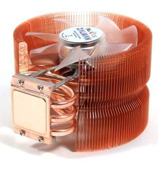
A heat sink is a term for a component or assembly that transfers heat generated within a solid material to a fluid medium, such as air or a liquid. Examples of heat sinks are the heat exchangers used in refrigeration and air conditioning systems and the radiator (also a heat exchanger) in a car. Heat sinks also help to cool electronic and optoelectronic devices, such as higher-power lasers and light emitting diodes (LEDs).
A heat sink is physically designed to increase the surface area in contact with the cooling fluid surrounding it, such as the air. Approach air velocity, choice of material, fin (or other protrusion) design and surface treatment are some of the design factors which influence the thermal resistance, i.e. thermal performance, of a heat sink. One engineering application of heat sinks is in the thermal management of electronics, often computer CPU or graphics processors. For these, heat sink attachment methods and thermal interface materials also influence the eventual junction or die temperature of the processor(s). Thermal adhesive (also known as thermal grease) is added to the base of the heatsink to help its thermal performance. Theoretical, experimental and numerical methods can be used to determine a heat sink's thermal performance.
Contents[hide] |
[edit] Basic heat sink heat transfer principle
A heat sink is an object that transfers thermal energy from a higher temperature to a lower temperature fluid medium. The fluid medium is frequently air, but can also be water or in the case of heat exchangers, refrigerants and oil. If the fluid medium is water, the 'heat sink' is frequently called a cold plate.
To understand the principle of a heat sink, consider Fourier's law of heat conduction. Joseph Fourier was a French mathematician who made important contributions to the analytical treatment of heat conduction.[1] Fourier's law of heat conduction, simplified to a one-dimensional form in the x-direction, shows that when there is a temperature gradient in a body, heat will be transferred from the higher temperature region to the lower temperature region. The rate at which heat is transferred by conduction, qk, is proportional to the product of the temperature gradient and the cross-sectional area through which heat is transferred.


Consider a heat sink in a duct, where air flows through the duct, as shown in Figure 2. It is assumed that the heat sink base is higher in temperature than the air. Applying the conservation of energy, for steady-state conditions, and Newton’s law of cooling to the temperature nodes shown in Figure 2 gives the following set of equations.
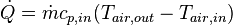 (1)
(1)
 (2)
(2)
where  (3)
(3)
Using the mean air temperature is an assumption that is valid for
relatively short heat sinks. When compact heat exchangers are
calculated, the logarithmic mean air temperature is used.  is the air mass flow rate in kg/s.
The above equations show that
- When the air flow through the heat sink decreases, this results in
an increase in the average air temperature. This in turn increases the
heat sink base temperature. And additionally, the thermal resistance of
the heat sink will also increase. The net result is a higher heat sink
base temperature.
- The increase in heat sink thermal resistance with decrease in flow rate will be shown in later in this article.
- The inlet air temperature relates strongly with the heat sink base temperature. For example, if there is recirculation of air in a product, the inlet air temperature is not the ambient air temperature. The inlet air temperature of the heat sink is therefore higher, which also results in a higher heat sink base temperature.
- Therefore, if there is no air or fluid flow around the heat sink, the energy dissipated to the air can not be transferred to the ambient air. Therefore, the heat sink functions poorly.
- Furthermore, a heat sink is not a device with the "magical ability to absorb heat like a sponge and send it off to a parallel universe"[2].
Other examples of situations in which a heat sink has impaired efficiency:
- Pin fins have a lot of surface area, but the pins are so close together that air has a hard time flowing through them.
- Aligning a heat sink so that the fins are not in the direction of flow.
- Aligning the fins horizontally for a natural convection heat sink. Whilst a heat sink is stationary and there are no centrifugal forces and artificial gravity, air that is warmer than the ambient temperature always flows upward, given essentially-still-air surroundings; this is convective cooling.