SOUND CARD AND USB SYSTEMS SECRETS |
|||||||||||||||
   USB systems  What is a USB?The Universal Serial Bus was invented and standardized by a group of computer and peripherals manufactures in 1995. The idea was to take the whole area of serial port and serial bus and update it with the twenty-first century technology. It is true that there were many standards of communication between host computers and peripherals, but the goal was to create a technology that combines low speed and high speed bus activity. The technology enables shared access for both speeds, a technology which provides robust protocol, automatic configuring of devices and a serial bus which is simplified and easy to plug into. All those requirements were met with the USB standards. The USB has become a very popular expansion to the personal computer. It is important to remember the USB isn?t a serial port it is a serial bus, a fact that enables a single port on the computer to be a link for a myriad of devices, (up to 127 devices in a USB system). We can easily chain one device to another and use one port as a connecting point of many devices by using a hub. All these enables us to look at the USB system as a small network of devices. The plug and play capability of the USB is one of its advantages over other serial buses. This capability enables automatic detection of a new device, which is attached into the system, an automatic configuration of it by the host, and an automatic detection of it's detachment from the system. The flexible attachment and detachment of devices to and from the system allows mobility on the bus and adjustment of the system to new devices without the need of restart the whole system each time a new device is detected. Another important aspect of the USB is it's mid and high speed flexibility. This feature refers to the ability of the USB to support simultaneously medium-speed devices, (which work in 1.5Mbps), and high-speed devices, (which work in 12Mbps). The simultaneously work of the USB system finds expression also in the dual support in both isochronous and asynchronous bandwidth allocation methods. Isochronous means that the necessary bandwidth is guaranteed, whenever the device requires it ? it will be available. Asynchronous on the other hand means that there is no guarantee ? the data will be sent whenever it will be possible to send it. Devices, such as video and audio multimedia, that use stream transfer, will use the isochronous method while devices that use bulk transfer, such as printers and scanners will use the asynchronous method. The USB is robust. Through all the different protocol layers there is an error detection and recovery mechanism, which guarantees low error rate. The USB provides detection of faulty devices and flow control mechanism, which is built in the protocol.
A typical USB system
A typical USB system consists of:
|
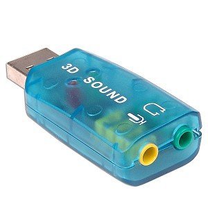
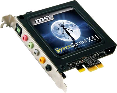
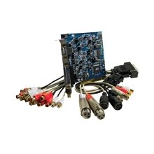
Sound card
A sound card (also known as an audio card) is a computer expansion card that facilitates the input and output of audio signals to and from a computer under control of computer programs. Typical uses of sound cards include providing the audio component for multimedia applications such as music composition, editing video or audio, presentation, education, and entertainment (games). Many computers have sound capabilities built in, while others require additional expansion cards to provide for audio capability.
[edit] General characteristics
Sound cards usually feature a digital-to-analog converter (DAC), which converts recorded or generated digital data into an analog format. The output signal is connected to an amplifier, headphones, or external device using standard interconnects, such as a TRS connector or an RCA connector. If the number and size of connectors is too large for the space on the backplate the connectors will be off-board, typically using a breakout box, or an auxiliary backplate. More advanced cards usually include more than one sound chip to provide for higher data rates and multiple simultaneous functionality, eg between digital sound production and synthesized sounds (usually for real-time generation of music and sound effects using minimal data and CPU time). Digital sound reproduction is usually done with multi-channel DACs, which are capable of multiple digital samples simultaneously at different pitches and volumes, or optionally applying real-time effects like filtering or distortion. Multi-channel digital sound playback can also be used for music synthesis when used with a compliance, and even multiple-channel emulation. This approach has become common as manufacturers seek to simplify the design and the cost of sound cards.
|
||||||||||||||

